ESA title

CONTACT US

Learning Hub The ESA Learning Hub is a web-based platform which provides access to training courses and materials linked to ESA programs and initiatives

Matchmaking ESA-Match is a platform that lets companies showcase their competences and capabilities, find partners, explore commercial opportunities and establish business relationships

Intellectual Property ESA makes its intellectual property available to European space companies within its 22 Member States, on a freely-licensed basis

ESA Patents

CONTACT US

    * Mandatory field

    PATENT CATEGORY

    REFERENCE #

    537


    PATENT COMPETENCE DOMAIN

    ABSTRACT

    ESA has developed a shield that can be retrofitted to existing GNSS (Global Navigation Satellite Systems) geodetic receivers that allows interference to be controlled, minimised, and even eliminated. This solution could benefit virtually all GNSS geodetic networks worldwide and ESA is looking for partners who would be interested in licensing and implementing the design.

    Description:

    One of the biggest issues that affects the performance of GNSS is the inability to control multipath and interference in the environment close to the antenna.  To this end, ESA has developed a shield to tightly control both the multipath and interference issues commonly observed at GNSS ranging stations.

    This solution provides the user with the ability to control the local radio frequency (RF) environment without requiring a re-design of the GNSS geodetic receiver, thus providing savings both in terms of cost and complexity. 

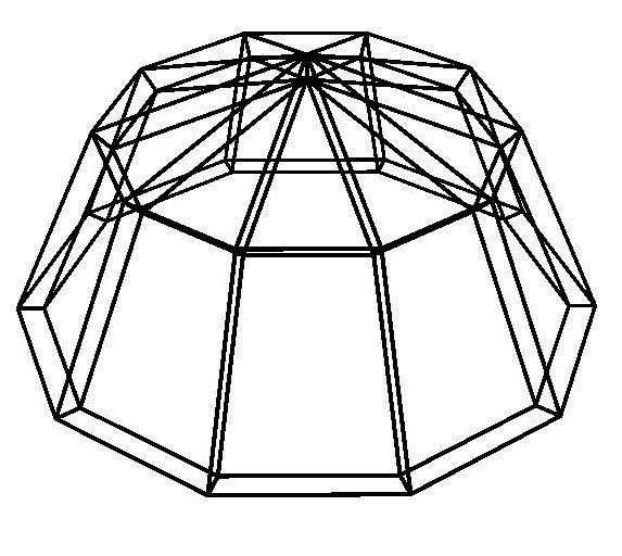
    The shield is based upon the principle that the RF-environment local to the antenna can be modified and controlled by having the receiver embedded within a geometrical structure. This structure is designed such that unwanted signals, both multipath and interference, are either absorbed completely or highly attenuated. The isolation of the receiver is achieved by utilising a combination of reflection, diffraction, and absorption. The exact configuration is determined by the angle of arrival, with respect to the local horizon, of the unwanted signals.

    The mechanical design of the shield allows for it to be operated in harsh weather conditions such as; heavy rain, high winds, and even snow without the performance being adversely affected.

    Overview of the shield's mechanical design
    Overview of the shield’s mechanical design

    Innovations and advantages:

    • Ability to retrofit to existing receivers without requiring extensive redesign
    • Reduced cost of total systems
      • For a GNSS service based on a single GNSS geodetic station, this shield would allow a given level of performance to be achieved with a simpler GNSS receiver.
      • For a GNSS service based on multiple GNSS geodetic stations, this shield would allow a given level of performance to be achieved with a reduced number of stations (using the same original GNSS receiver).
    • Ability to operate in harsh weather conditions

    Domain of application:

    • Virtually all GNSS geodetic networks worldwide could benefit from this shield
      • GNSS commercial positioning service providers
      • Research institutes
      • Developers of next generation GNSS services and solutions
    PATENT CATEGORY

    REFERENCE #

    568


    PATENT COMPETENCE DOMAIN

    ABSTRACT

    The European Space Agency (ESA) has developed a low weight compactly deployment method and support structure. This technology can be used in civil engineering and infrastructure such as deployable bridges, and towers or domes and roofs. License agreement collaborations are sought.

    The offered technology provides a low weight, compactly deployable support structure suitable for large deployable apertures. It is based on a bar-linkage structure, convertible from a deployed state into a folded state and vice versa. This concept allows the construction of unit cells of scalable and modular deployable structures with double curvature. This technology provides a deployment principle for support structures that enable a flexible modular architecture for building large apertures. Every strut is coupled to two others by a revolute joint forming a closed loop. The general concept of the folding scheme of a facet is depicted hereafter:

    Assemblies of facets can generate 3-D structures as the one shown:
    Assemblies of facets can generate 3-D structures as the one shown:

    Several cells can be connected in order to build a modular construction. The key to that feature is the kinematics of the joints between facets and modules.

    Concerning civil engineering applications, the cases of domes and large deployable buildings has been studied in some detail. As an example, the figure below shows a construction in a deployed state that could be either the dome of a large circular building or a large foldable tent, depending on the cross sections and dimensions of the bars. The kinematics of the deployment are as described for the space structures, with the difference of needing a central pole during the deployment that can be removed when deployed. The resulting double layers of bars or beams, provide stiffness and strength to the construction, as well as room for isolation in between the exterior roof and the interior concentric ceiling.

    Innovations and advantages:

    The offered technology improves actual folding / deploying structure methods.

    • The package size ratio can be optimised in order to transport the structures folded and deploy in-situ
    • The mass/stiffness ratio is improved
    • The deployment and folding processes are reversible
    • Complex shapes can be reproduced, with positive or negative curvature
    • Scalability allows to grow in size by employing conventional truss-structure principles
    • Modularity allows further growth, with reduced development costs

    Domain of application:

    This technology could be used in civil engineering and infrastructure construction.

    PATENT CATEGORY

    REFERENCE #

    578


    PATENT COMPETENCE DOMAIN

    ABSTRACT

    The European Space Agency (ESA) together with an SME and academies, has developed a deployable tensegrity structure with an diminished deployment failure risk. This technology can be used in communications applications such as antennas, for energy harvesting purposes as solar arrays structures, aquaculture structures or civil engineering deployable structures. Licence agreement collaboration is sought.

    Description

    The present invention relates to a deployable tensegrity structure. Tensegrity is a structural principle based on the use of isolated components, such as rigid bars or struts (in compression), linked together by a continuous net of cables or tendons (in tension), in such a way that the rigid bars or struts do not touch each other.

    The proposed structure comprises, in the deployed state, a ring shaped support structure around a longitudinal axis which comprises:

    • a first flexible tension member defining a first contour of said ring shape and a second flexible tension member defining a second contour of said ring.
    • a first group of rigid compression members extending between said first and second contours ,one end of each rigid compression member of the first group being mounted on the first contour whereas the other end is not mounted on a contour and a second group of rigid compression members extending between said first and second contours, one end of each rigid compression member of the second group being mounted on the second contour whereas the other end is not mounted on a contour. These first and second groups of rigid compression members are arranged with a repetitive crossing pattern around the ring.
    • a first plurality of flexible tension members linking each end of a compression member mounted on one of said contours to an end of another compression member which is not mounted on one of said contours and, a second plurality of flexible tension members linking each end of a compression member which is not mounted on a contour to an end of another compression member which is also not mounted on a contour.

    The deployment can be achieved by means of spring-based actuation system, housed in the compression members. During deployment the length of the flexible tension members outside the rigid compression members decreases. Once the deployment is achieved, latching devices inside the rigid members lock the flexible members in their final position.

    Innovations and advantages of the offer:

    The invention proposes a tensegrity deployable structure which is light, stable and reliable, especially when its deployment is considered.

    An advantage to use a tensegrity structure is to diminish the risk of failure of the deployment. In non-tensegrity structures, the joints between two rigid bars or struts raise the failure risks.

    Domain of Application:

    • Civil engineering
    • Satellite technology systems
    • Aquaculture
    • Solar/Thermal energy
    • Satellite ground
    • Solar energy
    • Photovoltaic solar
    • Agriculture, foresty. fishing…
    • Building construction.
    PATENT CATEGORY

    REFERENCE #

    596


    PATENT COMPETENCE DOMAIN

    ABSTRACT

    ESA has developed a novel mechanical support ring structure. Originally developed for supporting a deployable space reflector antenna, this technology has applications in support structures and collapsible constructions. The mechanical support ring structure is deployed from a folded, cylindrically stored state into a fully extended state. It can also be deployed in a cylindrical or conical shape. License agreements are sought.

    Description:

    The structure is aimed at being designed and constructed for large, deployable apertures that vary in size from 4 to 50 metres, whilst at the same time being able to be stored in compact and low mass containers. The design will provide high deployment process reliability, to a high level of accuracy. It is also intended to provide high stiffness and stability of the deployed support structure. In order to provide support of different instruments, the design can be deployed in either a cylindrically shaped structure, or a conically deployed one.

    This structure is deployed by using an actuator configured to pull a cable across the upper and lower pantograph rods, which extends the structure outwards.

    The design could be useful in quick assembly or pop-up structures, such as stands or tents.

    Innovations and advantages:

    • The ring can be stored in a small, low mass container and deployed to sizes up to 50m, or greater
    • High deployment process reliability and accuracy, more-so than conical equivalents
    • High stiffness and stability support structure
    • Less complex than conical mechanical support systems as found in prior art

    Commercialisation aspects:

    Applications and Markets
    The technology may be interested for applications such as pop up/quick assembly structures, support structures (e.g. for arrays), field hospital/disaster area structures or deployable solar arrays.

    Intellectual property status
    A PCT application has been filed. Looking for license agreements.

    PATENT CATEGORY

    REFERENCE #

    621


    PATENT COMPETENCE DOMAIN

    ABSTRACT

    This technology offers a new foldable / deployable lightweight structure that can be scaled to large antenna dishes or similar deployable structures. The key innovation is in the centralized electric motorization of the deployment structure as opposed to earlier variants that used multiple electric actuators within the structure. License agreements are sought.

    Description

    Deployable antenna structures exist in various forms and mechanisms, and the current technology is a further development of an existing deployable antenna. The deployment mechanism consists of a net in which the connections are formed by struts and cables, depending on their load in the deployed state. Cables are used where elements only carry tension, while struts are required where connections may carry compressive loads. The antenna surface itself is an elastic, foldable material that can be folded to small volume but will be stretched into a smooth reflective surface after deployment, in the required antenna dish shape. The shape is produced by a tension-bearing ring, formed by the bases of a series of foldable, triangular cells of the frame connected in their corners. The remainder of the deployed structure also consists of triangular cells that collectively define the precise shape of the antenna after deployment. 

    The innovative aspect of the current offer is that the entire deployment is driven by a central electrical motor, even if multiple structures are linked into a larger antenna. Conventional designs of similar deployable antennas typically involve multiple elastic elements for the deployment, In multiple locations of the structure.

    Innovations and advantages

    The key innovation is the central electrical deployment motor which does not need the assistance of multiple elastic elements throughout the deployable antenna. This leads to the following advantages:

    • easier manufacturing
    • lower cost
    • lower weight
    • simpler control of the deployment motion
    • reduced risk of mechanical failures
    • scalability of the structure into arrays of similar antennas

    Domain of application

    • Larger antenna dimensions than available from conventional designs
    • Mobile communications satellite services, mobile broadcast services and broadband satellite services
    • Radio astronomy based on very large baseline interferometry (VLBI)
    • Umbrella / parasol manufacturing up to large sizes (e.g. entire terrace)
    PATENT CATEGORY

    REFERENCE #

    635


    PATENT COMPETENCE DOMAIN

    ABSTRACT

    ESA has developed a method for deploying solar concentrators that fits within the standard frame of the solar panels. This system enables more light to be captured per area of solar panel thus improving the performance whilst reducing cost and weight. This deployment mechanism has applications both within space and back on Earth. ESA is looking for partners who would be interested in licensing and implementing this design.

    Description:

    Solar panels for space applications are very expensive and many methods and technologies have been employed in an attempt to improve their efficiency by increasing the amount of light gathered by a given number of cells. One of these technologies is solar cell concentrators – essentially foil panels either side of the solar panel that are angled such that they focus more incident light onto the photovoltaic cell. However, the majority of these have significant drawbacks when used in space either in terms of performance, cost, or lifetime. 

    ESA has developed a deployment and locking mechanism that fits within the frame surrounding a standard solar panel. It overcomes the performance issues caused by shrinkage which is common in the standard systems that depend on tethers to maintain alignment. 

    Deployed concentrators around solar panel
    Deployed concentrators around solar panel

    The mechanism is designed around the concept of deploying a solid strut using counter rotating cylinders joined by a cable. The strut is attached to a cable which is then wound around two cylinders in a figure of eight manner. When the central cylinder rotates anti-clockwise it induces a clockwise motion in the right-hand cylinder which in turn allows the strut to move out. Once the strut reaches the end of its travel it then becomes lodged between the left and centre cylinders.  (the strut with the dashed edge has only been shortened for drawing clarity – in the actual system it remains the same length.

    Figures 1-4 below show the deployment:

    Figure 1: Strut is in stowed configuration
    Figure 1: Strut is in stowed configuration
    Figure 2: Rotation of cylinders deploys strut
    Figure 2: Rotation of cylinders deploys strut
    Figure 3: Strut approaches end of travel
    Figure 3: Strut approaches end of travel

    For added rigidity in systems and structures that require it, tethers can be attached to the far end of the strut from additional cylinders (see Figure 5).

    Figure 4: Strut locks in place against both cylinders
    Figure 4: Strut locks in place against both cylinders
    Figure 5: Tether from additional cylinder to end of strut
    Figure 5: Tether from additional cylinder to end of strut

    The mechanism is replicated on the opposite ends of the cylinders and a reflective foil is spread between the two struts. Prior to deployment this is wrapped around the centre (orange) cylinder. Depending on the exact application an appropriate insulation layer can be added as a backing to the foil. This prevents warping of the foil due to the temperature differential between the two sides.

    System in stowed position showing strut and foil wrapped around cylinder
    System in stowed position showing strut and foil wrapped around cylinder

    Innovations and advantages:

    • Reduced overall system cost
      • More power per solar panel
      • Reduced weight
    • Reduces dependency on tethers that can contract/expand
    • Fits within frame of standard solar panel
    • Can easily accommodate different thermal insulation layers
    • The manner in which the strut finishes its journey result in low latching shocks.


    Domain of application:

    • Telecommunications Satellites
      • Large arrays of solar panels could be supplemented or partially substituted
    • Small sats/cube sats
      • Improve energy harvest whilst maintaining low weight and cost
    • Terrestrial Applications
      • Compact, deployable structures for advertising/exhibition stands
    PATENT CATEGORY

    REFERENCE #

    642


    PATENT COMPETENCE DOMAIN

    ABSTRACT

    The proposed invention is a filter to be used in fluidic systems to trap contaminants, preventing them from reaching components sensitive to contamination.

    Description

    Multi-layer mesh filter for fluids with an improved structure that maximizes the surface and prevents particle build up. The filter is obtained by an additive manufacturing process and, thanks to this, some unique features can be achieved. The main feature is that the filter is a single piece, which provides advantages such as avoiding weld joints, reducing the manufacturing time and avoiding spread of filter passages found in wire mesh filter elements. Furthermore, the filter is manufactured with a Titanium alloy, which makes it corrosion resistant. However, other materials are possible if they are more appropriate for specific applications.

    More information about the advanced fluidic filter can be found here

    Innovations and advantages:

    Due to limitations in the manufacturing process of in-line fluidic filters, these products have always been manufactured as an assembled group of pieces. For some applications, this technique and the results obtained may be suitable, but for other applications, a higher quality of the final product is needed. Thanks to the rise of additive manufacturing, older manufactured products can be redesigned and highly improved, both in terms of materials and functionality. This invention proposes a filter with the following features: 

    • High corrosion resistance.
    • Light weight.
    • Monolithic, built in one single piece, which allows avoiding weld joints, CTE (coefficients of thermal expansion) mismatch associated with the usage of components of different materials, movement and associated dislocation or wear of filter components, and spread of filter passages found in wire mesh filter elements.
    • Multi-lobe cross-section that maximizes the surface and minimizes the filter clogging and pressure drop.
    • Fluted cone tip of the filter that disperses the fluid, preventing particle build up at the entrance of the filter and spreading them through the whole surface.
    • Multi-layer mesh, which has a pattern displacement from layer to layer to reduce the size of contaminants that can pass through the filter and also prevent the passage of long slender contaminants.

    Commercialisation aspects

    Applications and Markets

    This technology can benefit those applications in which a fluid shall be filtered from pollutants or impurities. The main markets and applications include:

    – Aeronautics and automotive sectors for fuel impurities removal.

    – Chemical industry applications such as for high pressure liquid chromatography systems, capillary based systems.

    – Industrial biotechnology for example on enzyme production.

    – Thermo-nuclear plants (cooling systems). 

    Intellectual property status

    An international patent application has been filed.

    Sectioned filter prototype
    Sectioned filter prototype
    PATENT CATEGORY

    REFERENCE #

    767


    PATENT COMPETENCE DOMAIN

    ABSTRACT

    The present invention proposes a novel bearing system consisting of a static gas bearing driven by an ultrasonic membrane pump. The gas bearing offers low mechanical noise and excellent lifetime. Its distinct features make it particularly suited for the use in spacecraft attitude control actuators, for example Reaction Wheels, Momentum Wheels, or Control Moment Gyroscopes. ESA is looking for partners who would be interested in licensing and implementing this patent.

    Description:

    The peculiarities of space make the bearing choice in spacecraft difficult. Commonly encountered requirements are a maintenance-free operation for more than a decade, the tolerance against the degradation of fluid lubricants due to outgassing, radiation and other effects, the need for low friction caused by limited electrical power, and robustness against the high loads that the bearing has to sustain during the launch of the spacecraft.

    State-of-the-art Reaction Wheel technology is mainly based on rolling element bearings, which have a number of disadvantages:

    • The tribological contact between ball, raceways and cage requires constant lubrication.
    • The small contact area between raceways and rolling elements leads to high Hertzian contact pressures. Ball bearings are consequently sensitive to overload conditions which could deform either the rolling elements or the raceways.
    • Ball bearings provide little mechanical damping through their direct ceramic-to-metal or metal-to-metal contact, transmitting (unwanted) mechanical vibrations.
    • Manufacturing tolerances of rolling element bearings cause unwanted mechanical vibration and noise.
    • The lubrication function of the liquid lubricant is only guaranteed above a threshold speed of approximately 200 rpm.

     To overcome those disadvantages, this gas bearing system is presented. Figure 1 illustrates the elements of the invention, which consists of a combination of: 

    1. A static gas bearing.
    2. An ultrasonic pump (located inside the sealed compartment) as gas supply.
    3. A hermetically sealed compartment.
      For operation in the vacuum conditions of space, a hermetically sealed housing is required to maintain the working gas present throughout the lifetime of the spacecraft. Potential gas leakage can be avoided by reducing the number of flanges and parts to an absolute minimum. In any case, a sealed access lid is required to allow the assembly and repair of components inside the housing.
    4. A low pressure, low viscosity gas inside the compartment, to minimize areodynamic losses.
      A reduction in gas pressure will not only reduce aerodynamic losses, but also reduce the absolute pressure at the pump inlet.
    Scheme of the gas bearing system
    Scheme of the gas bearing system

    Innovations and advantages:

    • No fluid lubrication is required, avoiding any problem stemming from lubricants such as lubricant loss, evaporation, degradation, creep.
    • Excellent dynamic behaviour.
    • The vibration and noise emission of the gas bearing Reaction Wheel is 10x – 100x lower than the emission of a ball bearing Reaction Wheel.
    • Friction torque noise is absent in gas bearings, leading to a better spacecraft pointing stability.
    • Allow the reaction wheel to operate at higher speeds than +/- 200 rpm while maintaining good stability and performance.
    • Practically unlimited lifetime due to the absence of physical rotor-stator contact.
    • Considerably simpler to build than Magnetic Bearing Reaction Wheels as the part count is lower, the manufacturing requires standard tools and processes and the assembly process can be automated.
    • The electronics for the micropump are considerably simpler than the one for a Magnetic Bearing Reaction Wheel.
    • Cheaper and lighter than Magnetic Bearing Reaction Wheels.

    Domain of application:

    For many mission types the reduction of microvibration is a key aspect to achieve mission objectives. This includes various Earth observation, Science and (optical) telecommunication missions, i.e. missions with stringent fine pointing requirements. 

    A gas bearing type reaction wheel, if successfully qualified, would be a very attractive solution, since it would be less bulky, less complex, but more performant than current concepts. 

    Further, the combination of a vibrationless micropump and a static gas bearing could be interesting in the field of precision engineering, specifically in applications where the supply of pressurized gas for gas bearings is difficult to achieve. These could be autonomous sliders or bearings on flat floors etc.

    Keep updated on all ESA opportunities

    Subscribe to our newsletter or visit our Help page for quick answers

    Subscribe to newsletter Get Help